Pinch Clamp NozzleGreg Goett
Wednesday, August 03, 2005
Editor's note: Most regular readers of the sandcarving forum know Greg Goett by his 'handle' as "gregoryfairlane" (based on another life as a classic car restorer). Greg is a founding member of the Pacific Northwest Sandcarvers, and currently coordinates our workshops. In the article below, he describes his budget pinch clamp assembly, including detailed instructions on fabricating a nozzle that attaches to Bob Pickard style flexible hose. I've added a few words on the nozzle assembly, since I use a nearly identical device for fine sandcarving, with a footswitch to control abrasive flow instead of the pinch clamp. A primary difference in our designs, is that I run the tubing through the "compression fitting A 110", and seat the hose against the cone. This has the advantage of not exposing the brass fitting to the abrasive stream, prolonging its life. It does require that the compression fitting be drilled out, however.
About 3 years after making my original pinch clamp, I am finally getting around to writing up the process and parts required to make your own. The Pinch Clamp Nozzle below was developed for many reasons. 1) I'm cheap 2) My arthritic hands needed something that stayed open requiring no effort during long blasts 3) My need for an Engineering creative outlet
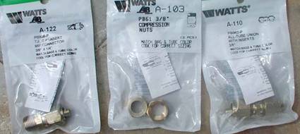
So what parts do you need to buy? Pinch Clamp (from local Beer and Wine making store, $2) Flexible hose (I bought mine from Bob Pickard. 1/4" ID.. $2/foot or so) (Please note that Bob's hose is NOT standard Tygon tubing. It is specially selected to resist abrasion. Please treat the hose with respect, especially where it is outside your cabinet, since abrasive under pressure can be a serious eye hazard, should the line or a fitting fail. Consider containing the tubing within a larger tube for outside the cabinet runs - ed) Compression Collar (the black rubber or plastic hose 1/2" ID (inside diameter). I cut a 1/8" wide strip for the collar. The brass compression rings that come with the brass compression fittings do not clamp to the blast hose well enough to hold pressure. You could cement the brass on or do what I did and buy a small hank of hose that is a snug fit over your blast hose. It goes inside the collar, and snugs up the tubing when you tighten the compression fitting. ) (ed: you can also choose to buy the white nylon ferrules that are made to replace the brass ones that come with the A-110 assembly) Compression Fitting A-110 (see below. The main body of the Blast nozzle assembly. It hold the hose to the Cone nozzle) Compression Nuts A-103 (see below, the compression nuts that come on the A-110 have the brass compression ring pressed into it. I probably could have knocked them out with a hammer, but the A-103s are cheap.) Compression fitting to 1/4" npt (national pipe thread) Fitting A-122 (for the other end of the blast hose, to adapt to your inlet hose or pressure pot. A similar fitting can be had 3/8 compression to 3/8 npt A-123 if you are using 3/8" thread on your pressure pot.)
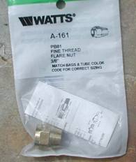
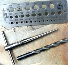
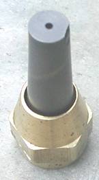
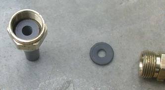
3/16 ID x 1/2 OD rubber washer. (obtained in small parts bins, 10¢. This forms a seal between the Compression fitting and the Blast Nozzle Cone Blast Nozzle (again I bought mine from Bob Pickard. At $20 each, it's as good a price as I've seen most anywhere) Last but not least A-161 Fine Thread Flare Nut. This needs to be modified to accept the Cone Blast nozzle. I just happened to have a great taper reamer (see picture) where I ream out the hole to fit. (The reamers cost about $15 at most hardware stores. I found mine in the plumbing department, since the reamer is used primarily to clean out the inside of small diameter pipe after it has been cut or threaded - ed) Drilling out the hole will work very satisfactorily. Drill the hole out with a 13/32" drill bit. If you do not have a drill bit that large, a dremel tool with a grinder should work. As long as you go slow and patiently.
Here is a picture of the drill bit and my (errrrr my dad's) reamer.
Notice how the tapered nozzle fits in the straight sided hole. It s fine. Just not overly professional.
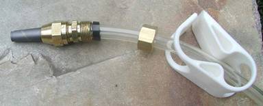
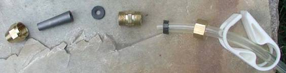
Here is the exploded view.
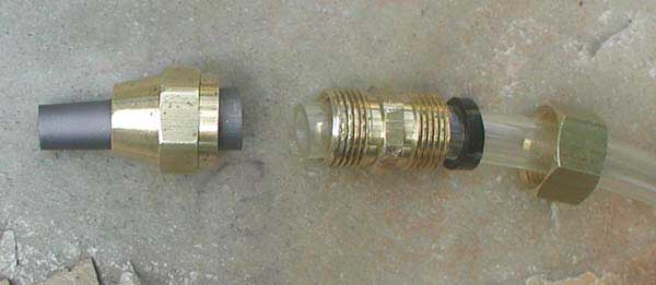
This one shows an alternative approach with the tubing running through the compression fitting. In this version, a ferrule could be used on the tubing on the left end of the compression fitting, and the rubber hose could be deleted.
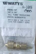
To make the smaller Pinch Clamp assembly, change to the smaller pinch clamp, the 1/8" ID hose (also from Bob P). and use Fitting A-109. The 1/4" ID hose works great as the compression collar.
|
|
©2005 Graydog Services • webmaster: jim(at)graydog(dot)org |